.svg)
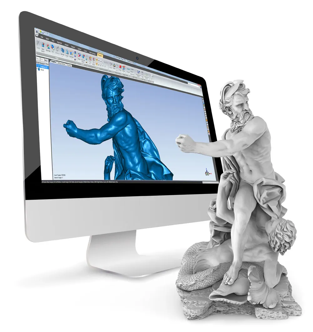
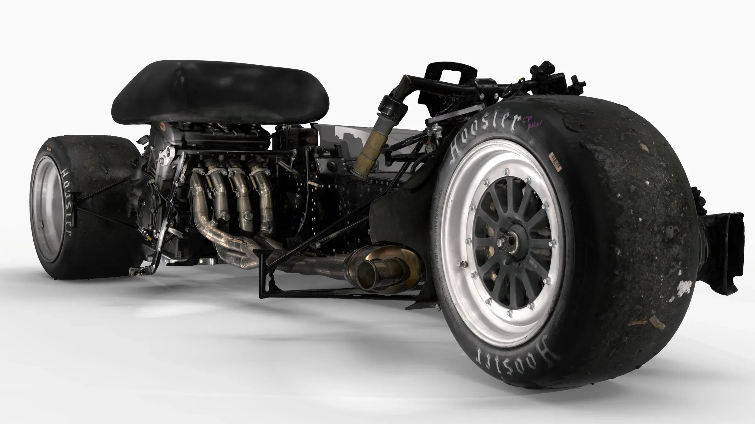
Competing in the FIM Sidecar World Championship, Kirby Racing are always looking for ways to develop their sidecar. Ahead of the 2026 season, the team came to us with a specific improvement in mind: redesigning the floorpan and fairing to close the gaps between them.
The aim was more aerodynamic grip, creating more of the “suck” towards the track that the team wanted through corners. Before designing the new surfaces, though, their engineers needed a detailed digital reference of the sidecar as it is now.
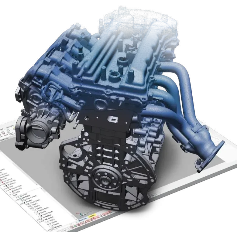
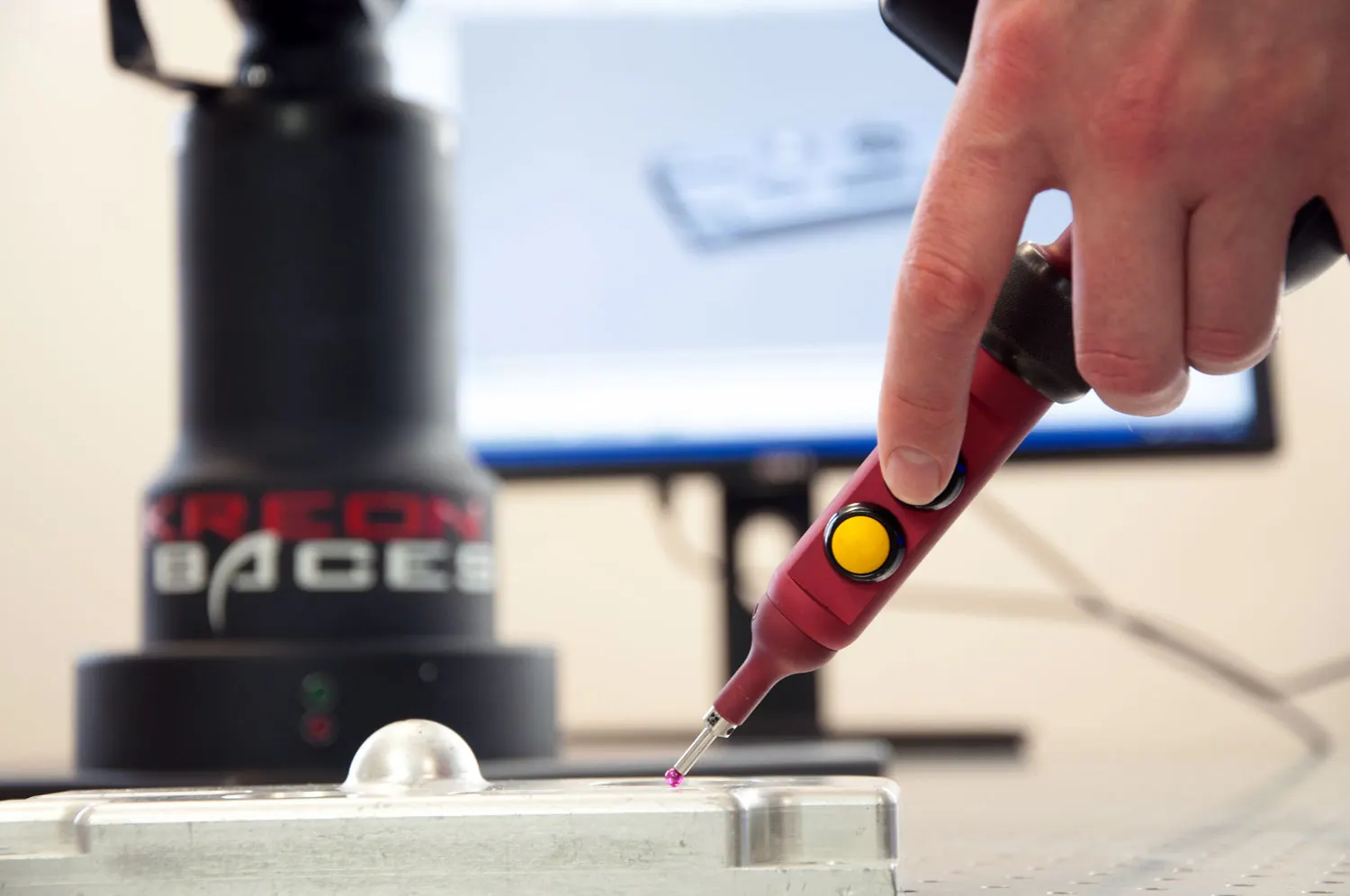
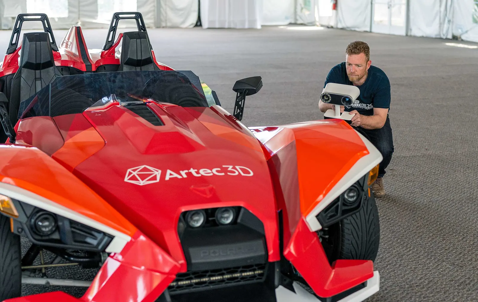
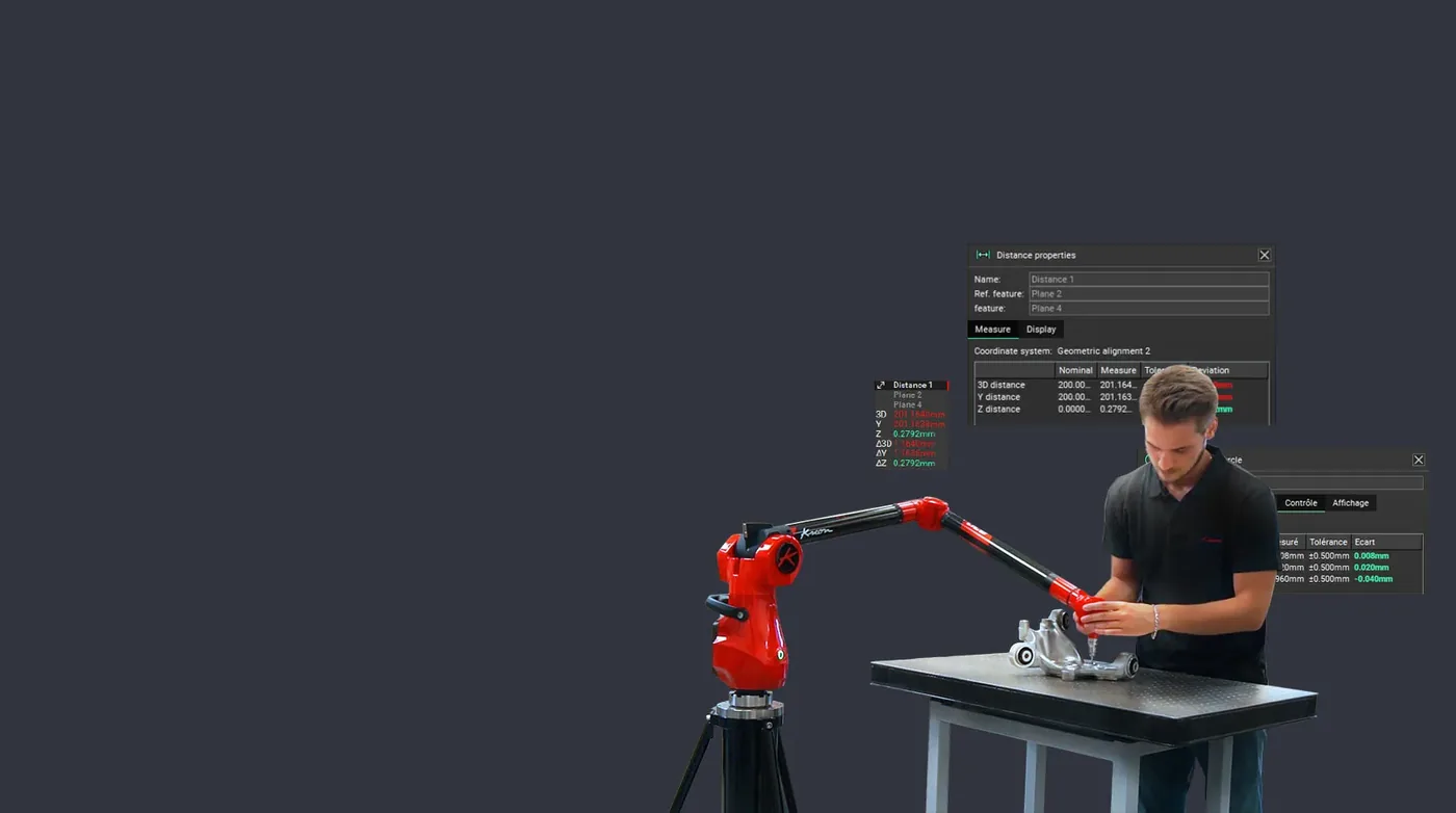
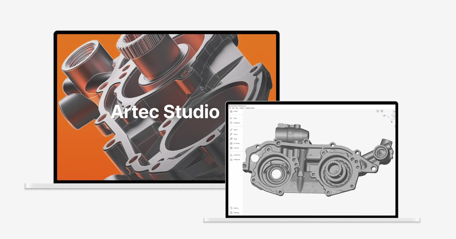
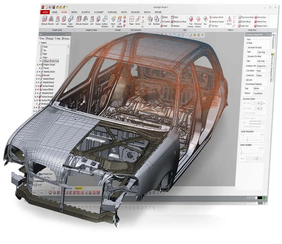
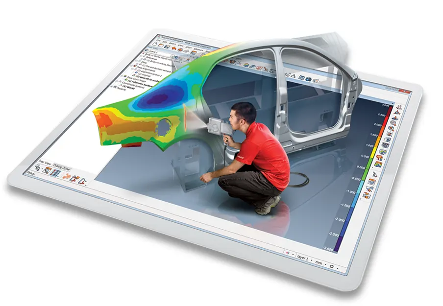
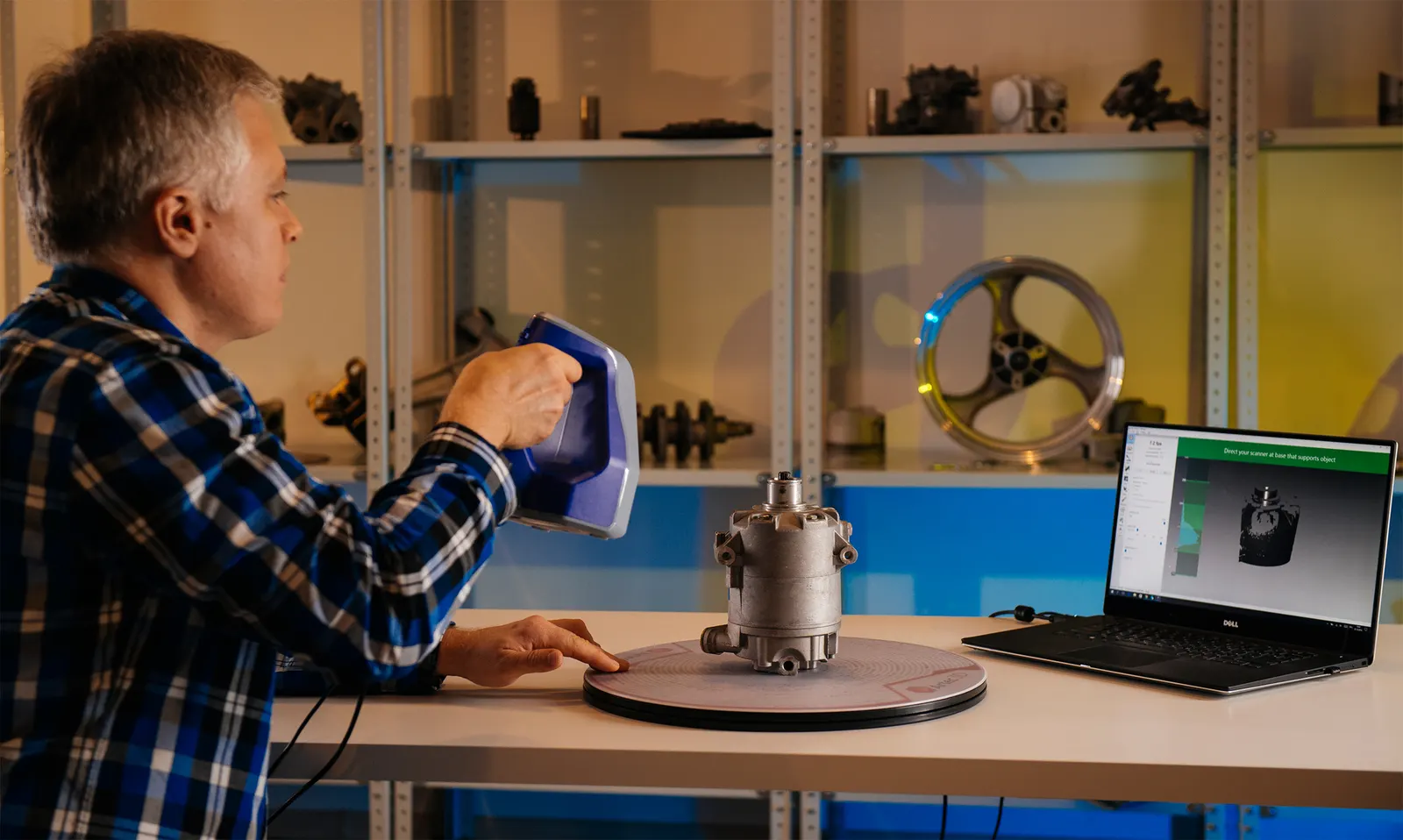
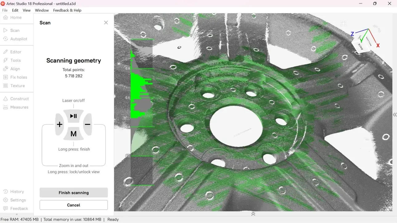
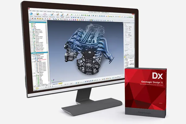
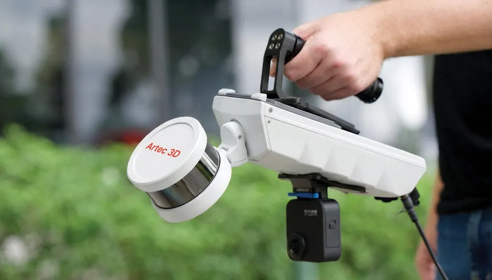
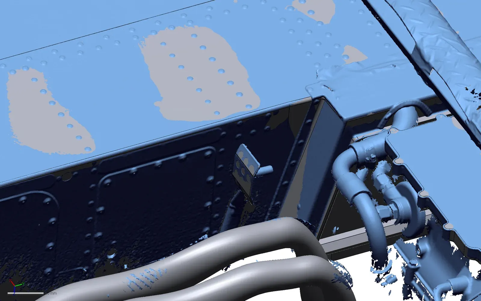
Our job was to capture that geometry and turn it into parametric CAD, giving the team a practical starting point for the redesign. We scanned the sidecar with the Artec Leo and Artec Point II and modelled it in Geomagic Design X.
Understanding the existing sidecar
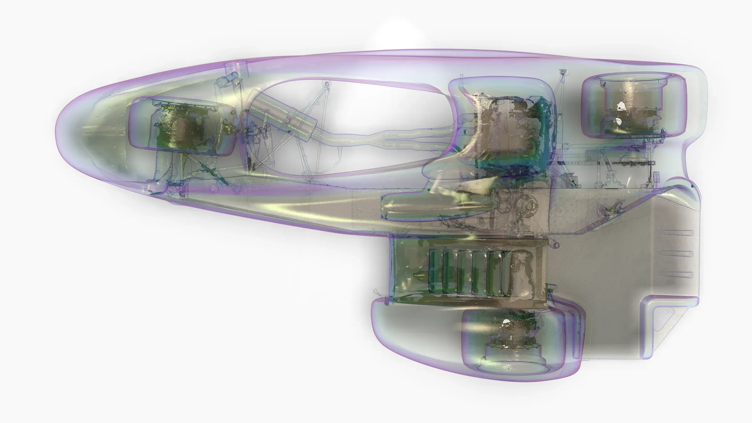
The floorpan and fairing had to fit more closely while still clearing the chassis, mounting points and surrounding components. Designing those changes meant understanding both the individual shapes and how they sit together in the assembly.
Measuring the curved bodywork and the complex underside by hand would have been slow. 3D scanning captured those surfaces in detail and gave the engineers a reference to work from throughout the design.
The project covered the driver and passenger floors, the inside and outside of the fairing, the airbox, and the chassis and subassembly geometry around them.
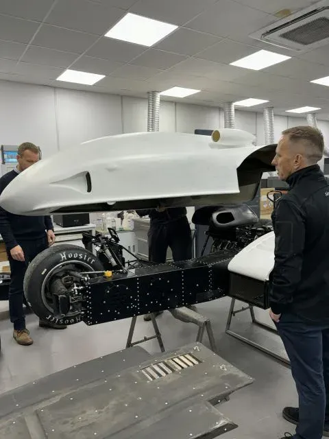
Capturing the geometry before the season
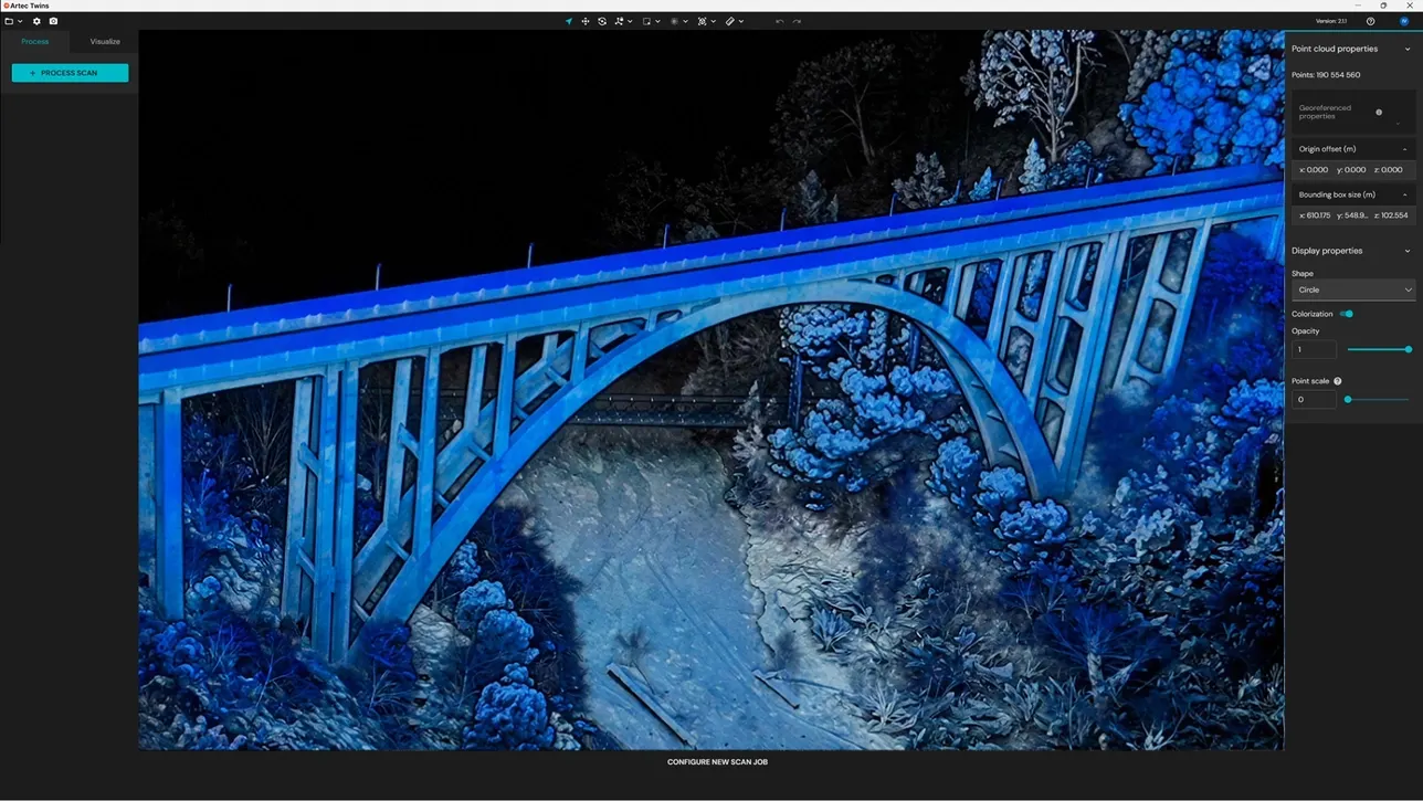
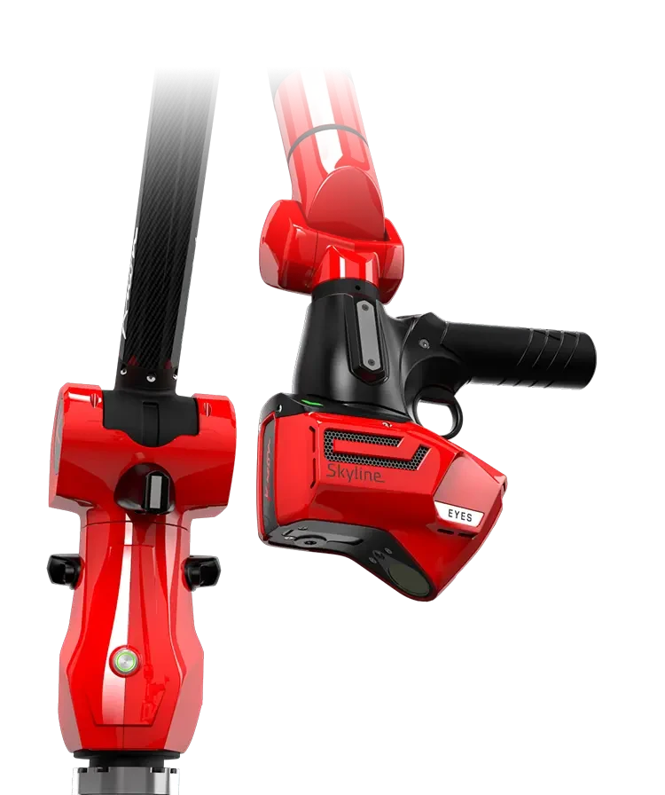
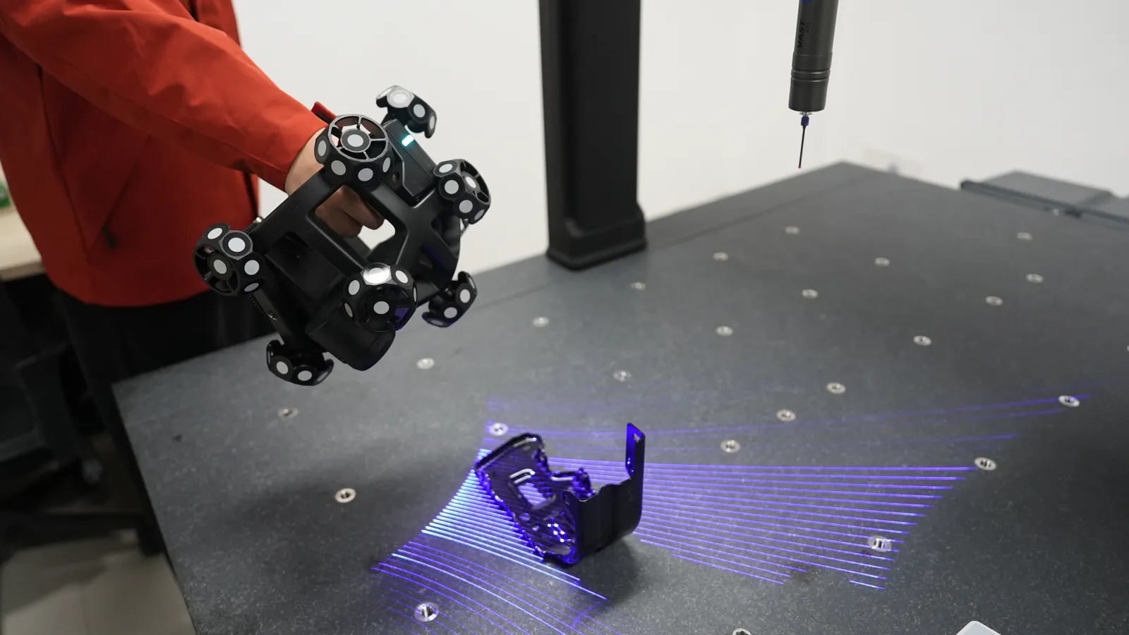
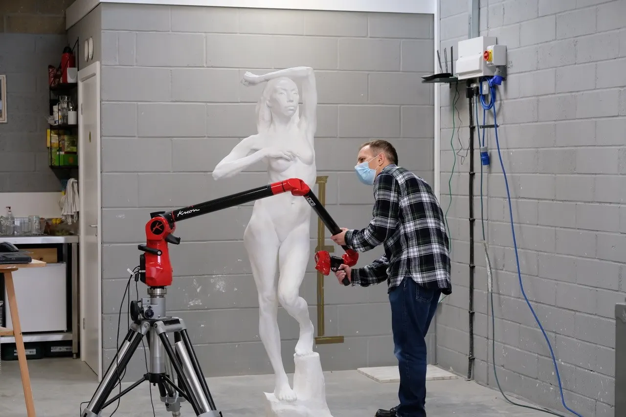
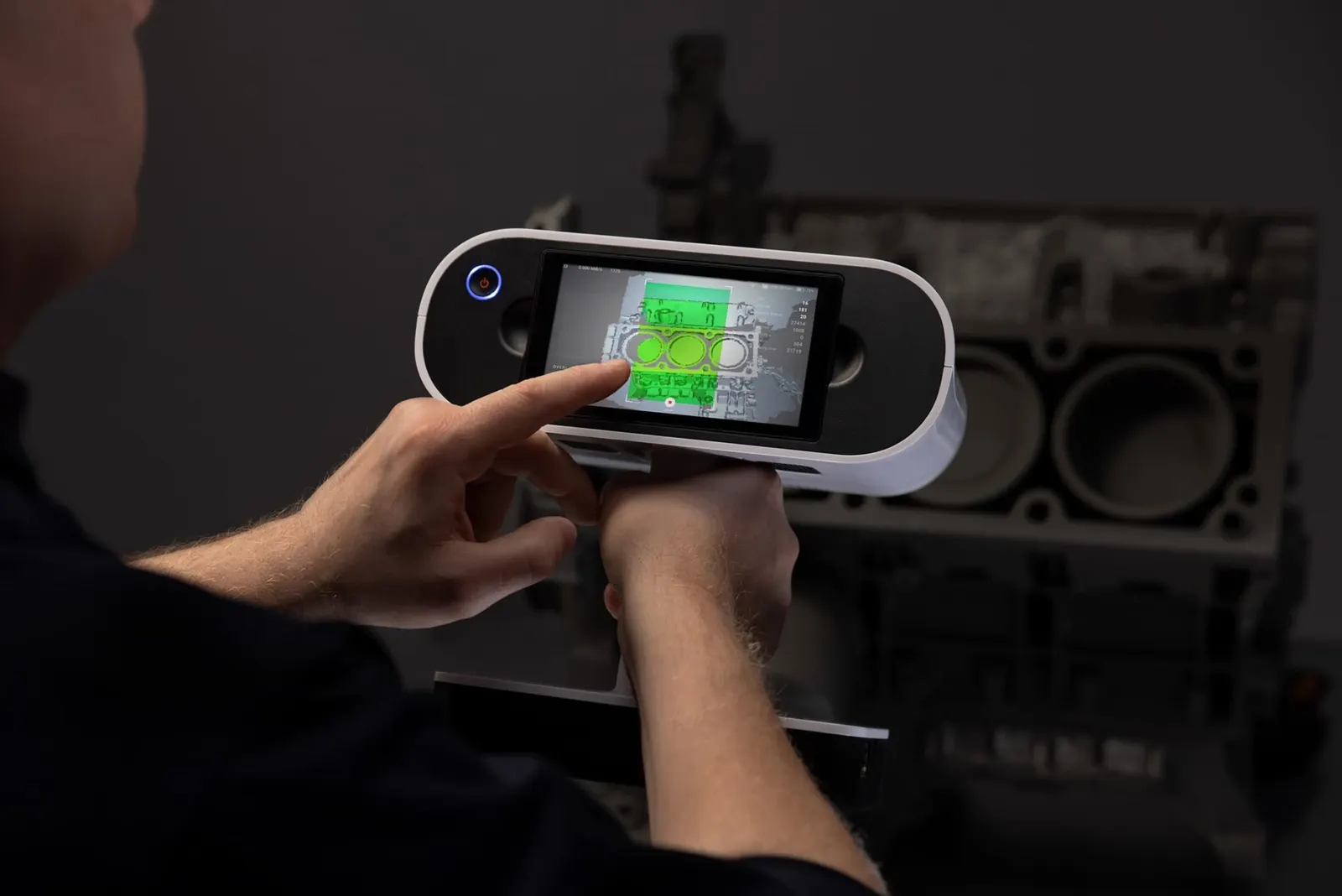
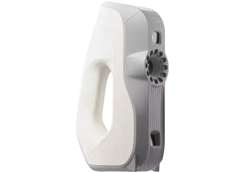
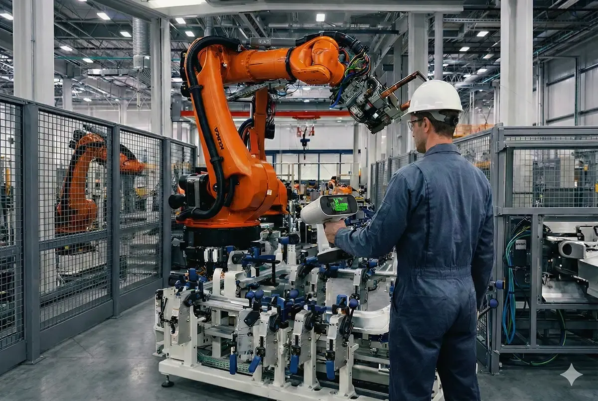
At the start of 2026 we scanned the sidecar components. The Artec Point II, a metrology-grade laser scanner, captured the fine features and tight areas, such as the exhaust and frame. The Artec Leo, a wireless handheld scanner, captured the large panels and bodywork, and the parts that stay fitted were scanned where they sit so their positions were kept.
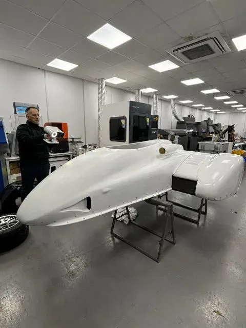
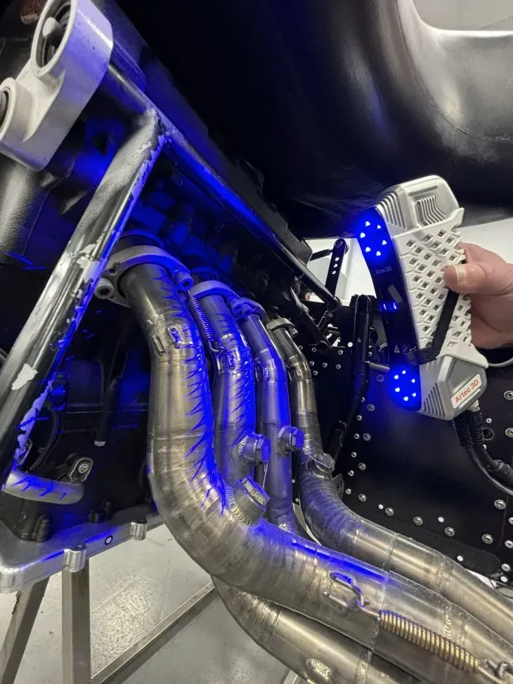
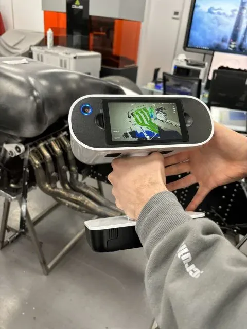
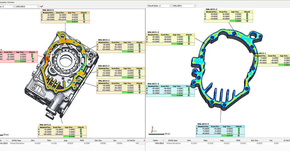
The scans were processed into detailed 3D meshes, recording the real surfaces and giving us a measured reference for rebuilding the parts in CAD. For Kirby Racing, that meant the redesign could start from the actual sidecar, including the profiles and interfaces the new floor and fairing had to meet.
Turning scan data into editable CAD
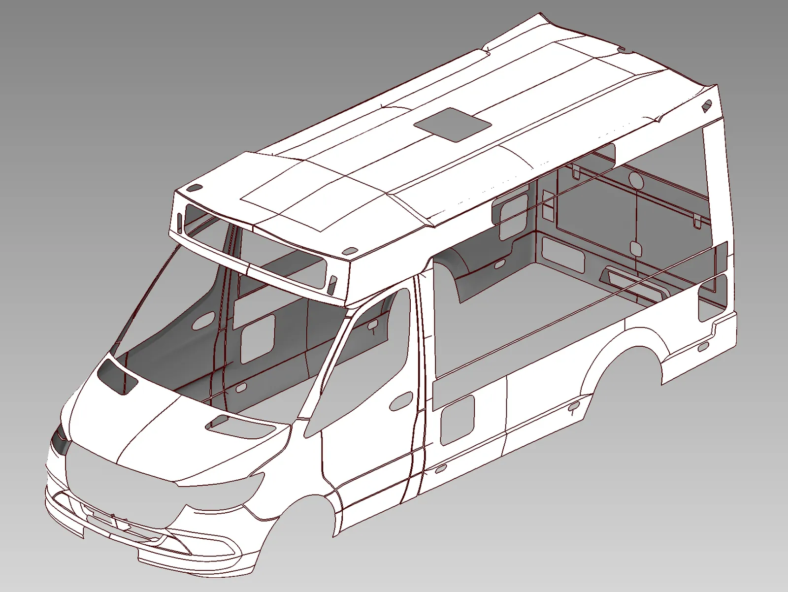
In Geomagic Design X we rebuilt the scanned components as parametric solid CAD, with the meshes as the reference for their shape and dimensions.
That gave Kirby Racing’s engineers editable geometry to design with. They could change profiles, extend surfaces towards the adjoining parts and check how the proposed changes fitted round the existing structure.
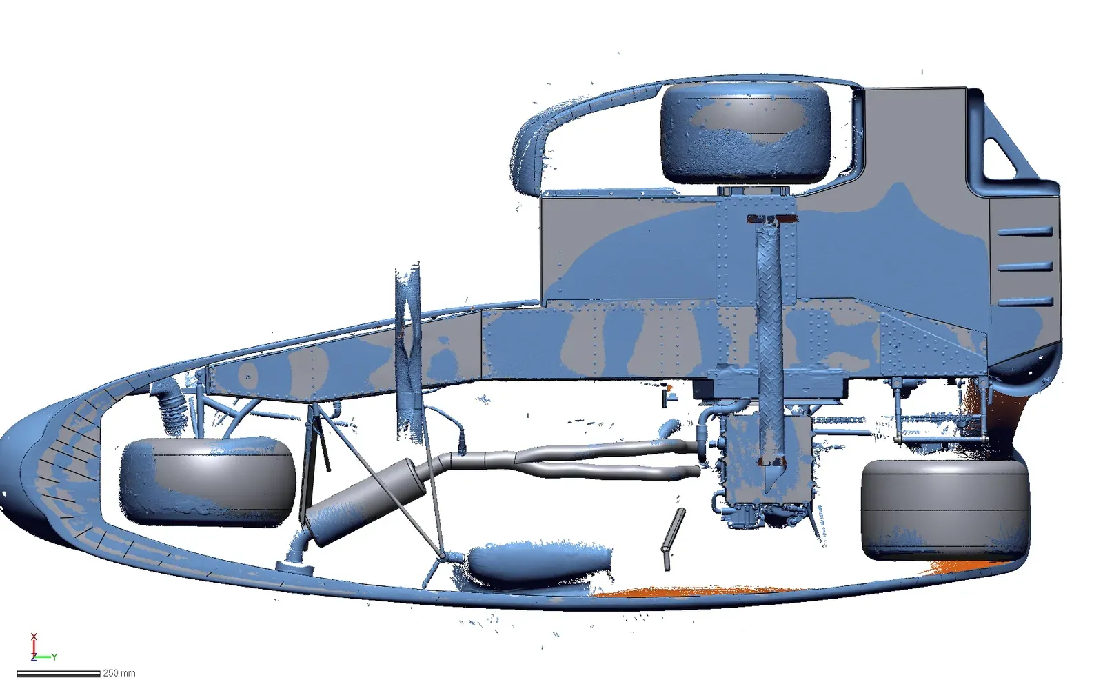
Each stage did a different job. The scans recorded what was there; the CAD gave the team the tools to change it.
Closing the gaps between the floorpan and fairing
With the existing geometry in CAD, Kirby Racing could work towards a more closely integrated floor and fairing. Filling the gaps between those surfaces was part of the team’s aerodynamic development, aimed at better ground effect and more grip through corners.
The CAD let the engineers design those changes in context. They could see where surfaces needed to extend, how adjoining edges would meet and where clearance was needed round other components.
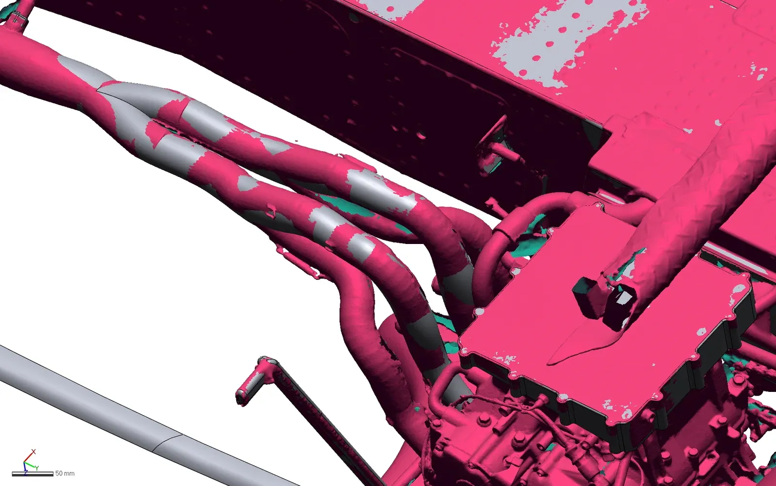
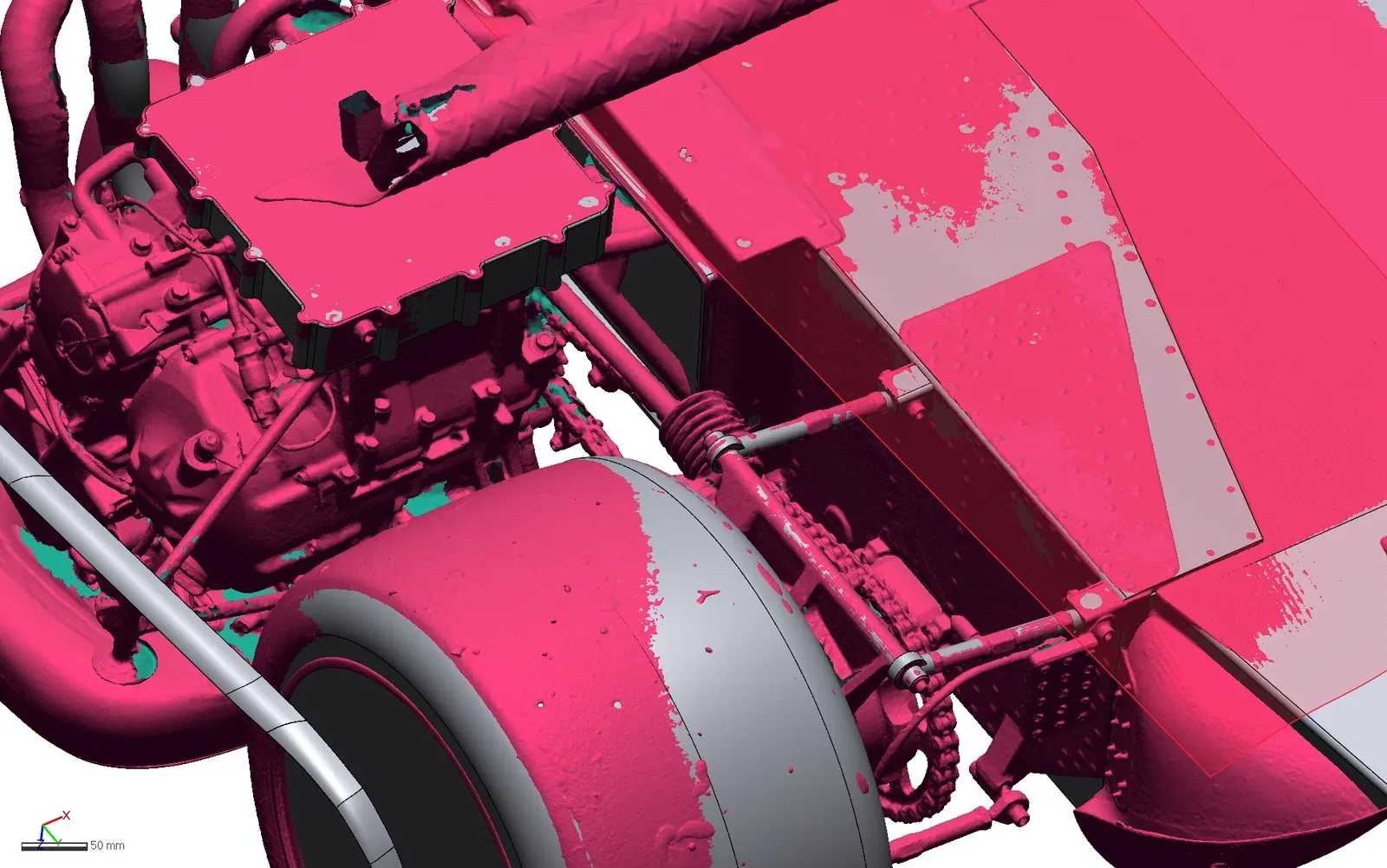
Our scanning and reverse engineering gave the team the foundation. They could then take the revised design through manufacture and testing to see how it performs on track.
More than an engineering reference
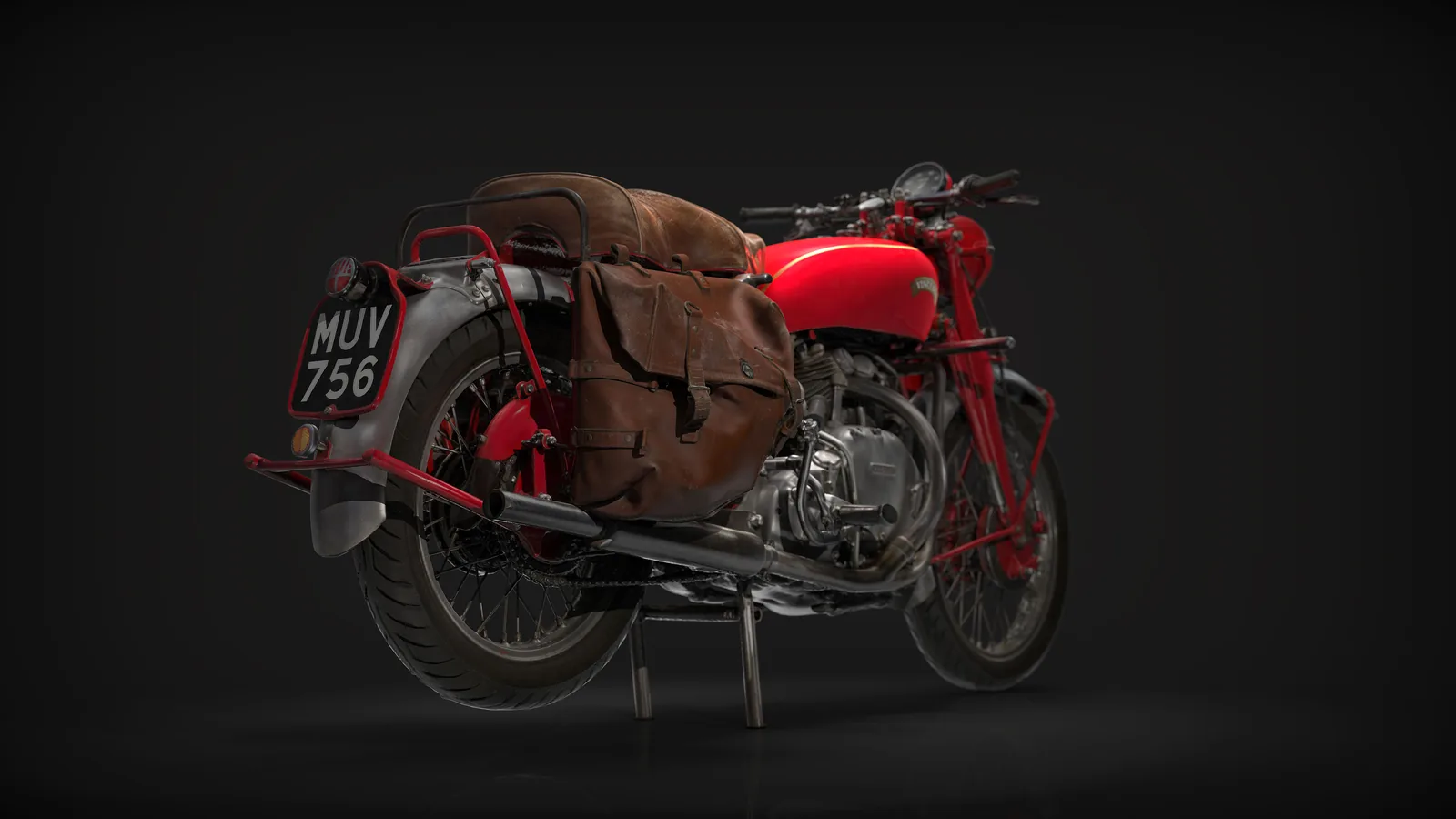
The immediate purpose was the redesign, but the same digital geometry is useful beyond engineering. With some preparation, the scan data and CAD can become visual content that helps a racing team present its work to sponsors and supporters:
3D renders. Detailed views of the captured components, with control over lighting, materials and camera angles.
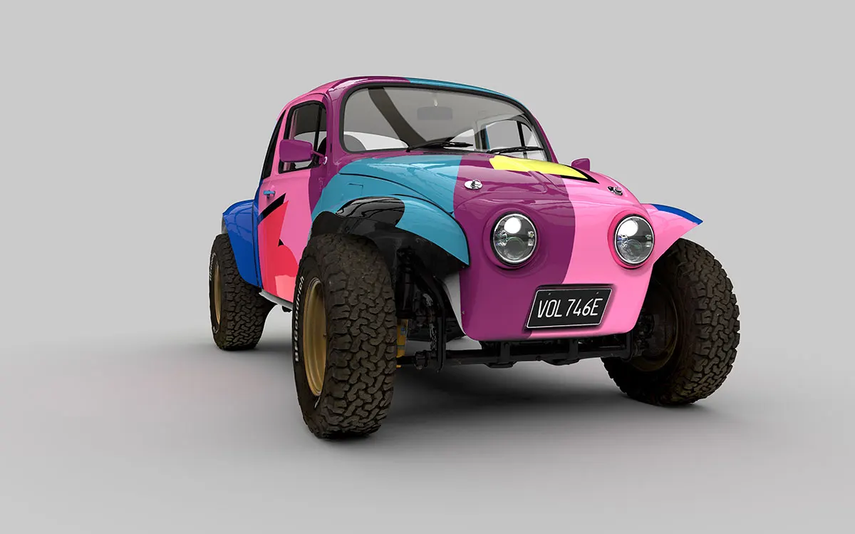
Livery and sponsor previews. Trying colour schemes and logo positions on the bodywork before the graphics are produced.
Advertising and promotion. Imagery for websites, brochures, banners and sponsor presentations.
Social media. Rotating models, component reveals and animations of the step from scan to CAD.
Technical illustrations. Showing how the floor, fairing and chassis fit together, and highlighting the proposed changes.
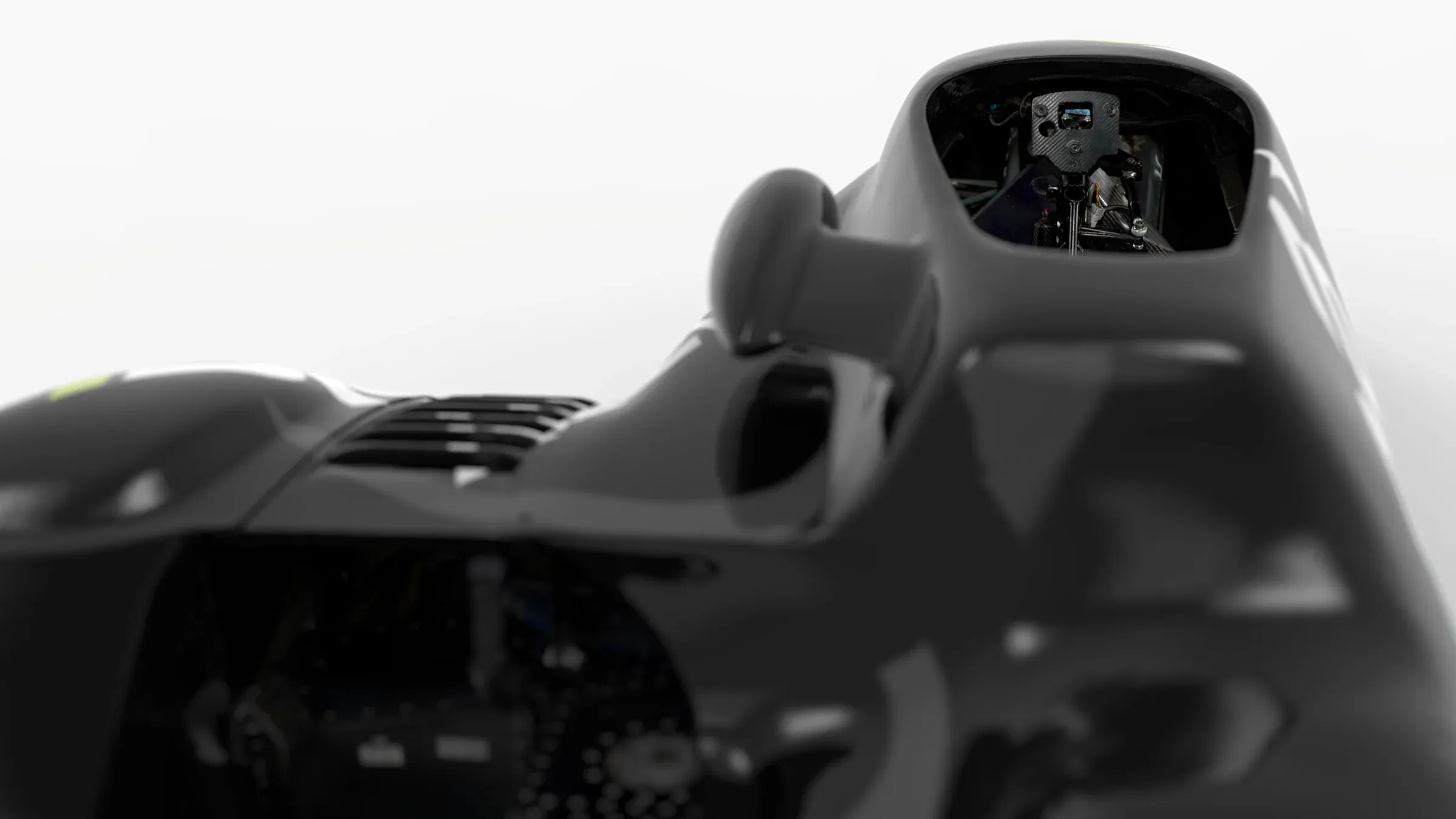
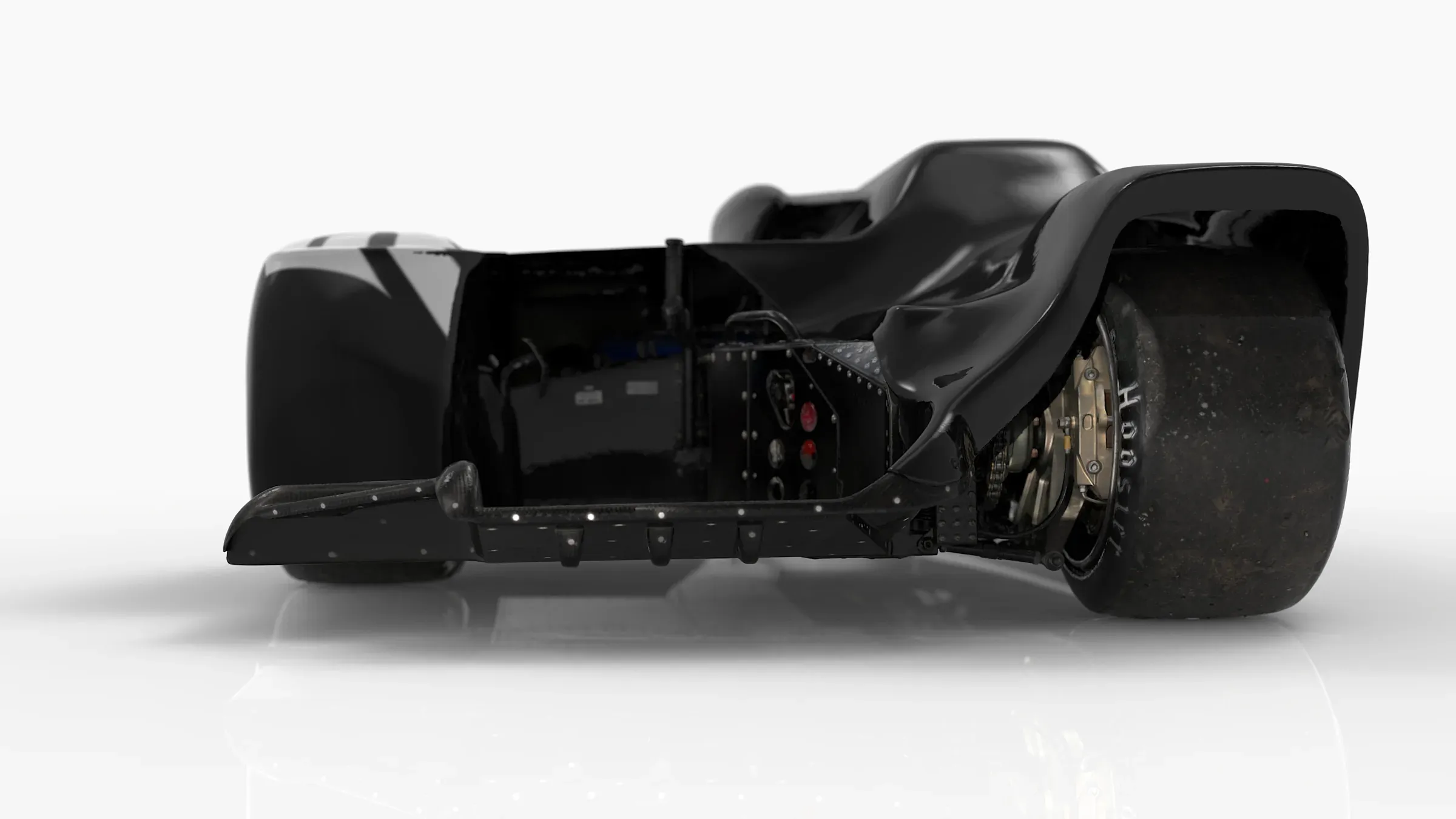
Each of these takes some extra modelling, materials and graphics to suit the output. The same data that supports a design decision can also help explain it.
A starting point for future development
The preseason project gave Kirby Racing a digital reference of their existing components and editable CAD for developing the new floorpan and fairing. That geometry can keep supporting future changes as the sidecar evolves.
It shows how 3D scanning and reverse engineering support product development: capture what exists, understand how it fits together, and use that to create the next design.
Developing new parts around an existing vehicle or assembly?
Our product redesign and modification service scans the parts you have and rebuilds them as editable CAD for your next design. Send us photographs of your components and a short description of the changes you want to make. Email sales@europac3d.com or get in touch.